
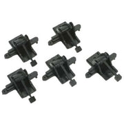
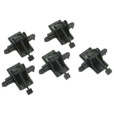
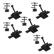
202S GROUND THROWS Sprung with .190 travel for HO and S, point levers CABOOSE INDUSTRIES


202S Sprung with .190" travel for HO and S
Instructions and Tips
General Installation of Ground Throws
Installing sprung Caboose Industries ground throws on a layout is straightforward.
1. Connect the slidebar on the ground throw to the throwbar on the turnout. Standard ground throws have pins to engage the throwbar; ground throws with selectable end fittings have a variety of connections appropriate for different commercial turnout models. Make sure the turnout throw bar and the ground throw slidebar are in a straight line, and that the slidebar and throwbar are free to move and will not bind when the ground throw is fastened in position.
2. Place the ground throw handle in the center position, so that it points straight up.
3. Move the ground throw back and forth until the switch points are half-way between the straight and curved position.
4. Mark the position of the ground throw in this center position.
5. Attach the ground throw to the roadbed with track nails, small screws, or spikes.
Use rigid Caboose Industries ground throws when the turnout and ground throw must be some distance from one another. Route spring wire through a tube from the turnout to the throw, and ensure that there is a spring mechanism to provide tension and allow for overtravel.
Assembling Ground Throws With Selectable End Fittings
-
Choose the end fitting that matches the brand of turnout you are using (hook end for Atlas, blade for Roco, hole for PECO, small round pin for Micro Engineering, and round pin for Shinohara and others). Do not remove it from the sprue.
-
Push the end fitting onto the receptacle end of the slide bar, using the sprue for extra leverage. The fitting connector has a "T" shape and the leg of the "T" goes down to engage the slot in the receptacle.
-
Make sure the fitting bottoms out with a slight snap when it is seated. No glue is required.
-
Now cut the fitting from the sprue.
The spacer plate can be used to raise the ground throw if it is not sitting on top of switch ties.
Assembling Ground Throws With Operating Low Level Targets (210S and 109R)
The basic throw mechanism comes preassembled. All the modeler has to do is assemble the target assembly. There are two methods for doing so:
-
Remove the gear and cover from the sprue. Be careful not to cut the hooks on the cover.
-
Raise the handle so it is straight up and down, in the middle of travel.
-
One side of the gear has a double diameter shaft, and the other has a single diameter shaft. Put the single diameter shaft through the hole in the cover and grab it with an alligator clip to hold it in place.
-
Center the gear on the rack gear attached to the slide bar.
-
Snap the cover to the base and ensure the gear and rack are engaged.
OR:
-
Remove the gear and cover from the sprue. Be careful not to cut the hooks on the cover.
-
Raise the handle so it is straight up and down, in the middle of travel.
-
One side of the gear has a double diameter shaft, and the other has a single diameter shaft. Put the smaller diameter pin on the double diameter shaft into the hole in the base.
-
Hold the base at an angle to keep the gear engaged with the rack gear.
-
Thread the cover over the single diameter shaft of the gear.
-
Snap the cover to the base and ensure the gear and rack are engaged.
No glue is required for the base assembly and glue will not adhere well to the Delrin parts.
To complete the target assembly:
-
Cut the target from the sprue.
-
Center the target on the shaft protruding from the cover.
-
Align the rectangular fins and two half ovals to the appropriate route.
-
Glue in place.
-
Paint the targets as required by the prototype railroad.
Optionally, the modeler may glue the supplied numbers to the top of the targets to identify the ladder tracks in a yard.
Assembling Ground Throws With Contact (220S, 119R, and 224S)
The basic throw mechanism comes preassembled. All the modeler has to do is assemble the contact.
-
Install the appropriate end fitting and mark the correct location for the ground throw as described above.
-
Drill a 3/8"-7/16" diameter hole below the ground throw to allow the three legs of the stationary contact to pass through the roadbed.
It is recommended that the modeler do the remaining assembly at the workbench, since it is easy to lose small parts.
-
Break the flat metal plate off the legs of the stationary contact by gently folding it back and forth.
-
Orient the stationary contact so that the high spot of the V-bends in the legs faces toward the slidebar.
-
Thread the legs through the slot in the ground throw so that the legs extend out the bottom.
-
Install the rigid hook on the stationary contact into the slot in the ground throw.
-
Push the stationary contact down into the ground throw until the flexible hook locks into the other slot.
-
Orient one of the phosphor-bronze moving contacts (the other is a spare) so that the slotted side faces the stationary contacts and the solid side fits into the pocket on the top of the slide bar.
-
Cut one of the two keepers from the small sprue that has two keepers and a spacer with three holes in it.
-
Note that the keeper resembles a "T" when viewed from one end. Grab the leg of the "T" with a locking forceps or wide-blade tweezers. Force the keeper into the pocket so that the smooth side locks the phosphor-bronze moving contact into place.
-
Slide the spacer with the three holes over the three legs of the stationary contact to keep them from shorting out.
-
Solder leads to the three legs of the stationary contact. Use the forceps as a heat sink on each leg to avoid transmitting excess heat to the plastic components.
-
Thread the leads and legs through the hole in the roadbed. Attach the ground throw to the turnout throwbar, then position and attach it as described above.
Assembling Hi-Level Switch Stands (204S, 103R)
The basic throw mechanism comes preassembled. The modeler may wish to install ground throw without the target until scenery is complete. To install the target:
-
Cut the 1/4" gear from the sprue.
-
Raise the handle so it is straight up and down, in the middle of travel, and the switchpoints are centered.
-
Install the gear in the hole in the top of the stand so that the gear is also centered.
-
Thread the brass rod through the hole in the gear and into the hole on the side of the stand base under the gear.
-
Secure the rod to the gear with a drop of ACC (super glue).
-
Cut the targets you wish to use from the sprue.
-
Move the switch stand handle to one end of its throw, and glue the target or targets onto the rod in the proper orientation.
-
After the glue dries, remove the gear assembly.
-
Paint the targets appropriately.
-
Reinstall the targets and gear into the switch stand.
-
Optionally, the modeler may attach the keeper under the top surface of the stand and secure it with a drop of glue. If the keeper is not installed, the modeler may remove the target and gear assembly during maintenance or cleaning; however it is also possible that the gears will become disengaged
You may also like...
-
 5202S GROUND THROWS Sprung with .190 travel for HO and S, point levers CABOOSE INDUSTRIES 5pk
Out of stock
5202S GROUND THROWS Sprung with .190 travel for HO and S, point levers CABOOSE INDUSTRIES 5pk
Out of stock
-
 5218S 5PK N or HO Caboose Industries: Type of Throw : Sprung Travel Dimensions : .165 inch.
$33.80
5218S 5PK N or HO Caboose Industries: Type of Throw : Sprung Travel Dimensions : .165 inch.
$33.80
-
 101R- Operating Ground Throw -- Rigid .190" Travel HO / S
$6.20
101R- Operating Ground Throw -- Rigid .190" Travel HO / S
$6.20
-

 105R- Operating Ground Throw -- .135" Travel Rigid - CABOOSE INDUSTRIES
$5.95
105R- Operating Ground Throw -- .135" Travel Rigid - CABOOSE INDUSTRIES
$5.95


Our brands